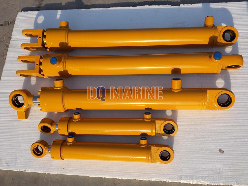
Rod End Male Thread and Head Eye Connecting:
Rod End Male Thread and Head Eye Connecting Description
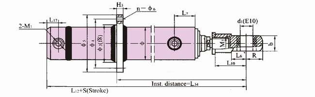
It is one kind of HSG series hydraulic cylinder, Rod end with male thread and the rod head with eye connecting.
Outline Installation Link Size
Eye Ring Connecting
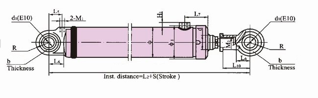
Eye Ring Connecting

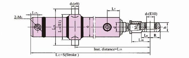
Trunnion Connection
End Flange Connection
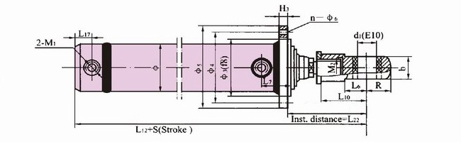
Middle Flange Connection
The Size table 1
| Cylinder bore D(mm) | Φ | d | d1 | R | b | L6 | M2 | L10 | L5 | L7 | L2+S | M1 | H1 | Φ1 | ||
| Speed Ratio φ | ||||||||||||||||
| 1.33 | 1.46 | 2 | ||||||||||||||
| 40 | 52 | 20 | 22 | # 25 | 20 or GE20ES | 25 | 30 | M16x1.5 | 50 | 30 | 65 | 255+S | M14x1.5 | 15 | 63 | |
| 50 | 61 | 25 | 28 | # 32 | 30 or GE30ES | 35 | 40 | M22x1.5 | 60 | 40 | 280+S | M18x1.5 | 72 | |||
| 63 | 73 | 32 | 35 | 45 | M27x1.5 | 65 | 295+S | 87 | ||||||||
| 80 | 99 | 40 | 45 | 55 | 40 or GE40ES | 45 | 50 | M33x1.5 | 80 | 50 | 75 &65 | 347+S | M22x1.5 | 18 | 107 | |
| 90 | 111 | 45 | 50 | 63 | M36x2 | 95 | 66 (76) | 357+S (377+S) | ||||||||
| 100 | 124 | 50 | 55 | 70 | 50 or GE50ES | 60 | 65 | M42x2 | 110 | 60 | 72 (82) | 402+S (422+S) | M27x2 | 20 | ||
| 110 | 137 | 55 | 63 | 80 | M48x2 | 115 | 77 (87) | 422+S (442+S) | ||||||||
| 125 | 149 | 63 | 70 | 90 | M52x2 | 140 | 78 | 452+S | ||||||||
| 140 | 165 | 70 | 80 | 100 | 60 or GE60ES | 70 | 75 | M60x2 | 155 | 70 | 85 (95) | 498+S (518+S) | ||||
| 150 | 177 | 75 | 85 | 105 | M64x2 | 160 | 75 | 92 (102) | 513+S (533+S) | M33x2 | 22 | |||||
| 160 | 191 | 80 | 90 | 110 | M68x2 | 170 | 70 | 100 | 533+S | |||||||
| 180 | 215 | 90 | 100 | 125 | 70 or GE70ES | 80 | 85 | M76x3 | 190 | 89 | 107 | 588+S | M42x2 | 25 | ||
| 200 | 241 | 100 | 110 | 140 | 80 or GE80ES | 95 | 90 | 95 | M85x3 | 210 | 100 | 110 | 628+S | |||
| 220 | 269 | 110 | 125 | 160 | 90 or GE90ES | 105 | 100 | 105 | M95x3 | 230 | 110 | 120 | 690+S | |||
| 250 | 294 | 125 | 140 | 180 | 100 or GE100ES | 120 | 110 | 120 | M105x3 | 250 | 122 | 135 | 754+S | |||
| Note: 1. () means the size when the speed ratio is 2 (φ=2) 2. # only means the speed ratio is 1.7(φ=1.7) 3. & only means key type sizes when the Φ=80mm 4. The stroke of trunnion connection can not smaller than the S1 in the table | ||||||||||||||||
The size Table 2
| Cylinder Bore D(mm) | L15 | L16 | L12+S | L17 | Φ3 | Φ4 | Φ5 | H3 | L22 | n-Φ6 | L33 | L34 | S1 |
| 80 | 125 | 185 | 322+S | 25 (Cylinder bore 90 with Cushing is 27) | 115 | 145 | 175 | 20 | 128 | 8-Φ13.5 | 260<L33<205+S | 245<L34<235+S | 45 |
| 90 | 140 | 200 | 332+S (352+S) | 130 | 160 | 190 | 134 (144) | 8-Φ15.5 | 275<L33<215+S | 260<L34<245+S | 50 | ||
| 100 | 155 | 230 | 372+S (392+S) | 30 (Cylinder bore 110 with Cushing is 32) (Cylinder bore 125 with Cushing is 35) | 145 | 180 | 210 | 150 (160) | 8-Φ18 | 310<L33<230+S | 290<L34<270+S | 50 | |
| 110 | 170 | 245 | 392+S (412+S) | 160 | 195 | 225 | 22 | 157 (167) | 8-Φ18 | 320<L33<250+S | 300<L34<285+S | 50 | |
| 125 | 185 | 260 | 422+S | 175 | 210 | 240 | 180 | 10-Φ18 | 335<L33<280+S | 315<L34<320+S | 40 | ||
| 140 | 200 | 290 | 463+S (483+S) | 35 (with cushing is 37) | 190 | 225 | 260 | 24 | 201 (211) | 10-Φ20 | 385<L33<305+S | 360<L34<345+S | 55 |
| 150 | 215 | 305 | 478+S (498+S) | 40 | 205 | 245 | 285 | 26 | 207 (217) | 10-Φ22 | 400<L33<320+S | 380<L34<360+S | 65 |
| 160 | 230 | 320 | 498+S | 35 (with cushing is 43) | 220 | 260 | 300 | 28 | 217 | 10-Φ22 | 410<L33<340+S | 390<L34<380+S | 60 |
| 180 | 255 | 360 | 548+S | 49 | 245 | 285 | 325 | 30 | 238 | 10-Φ24 | 455<L33<365+S | 430<L34<410+S | 75 |
| 200 | 285 | 405 | 578+S | 50 | 275 | 320 | 365 | 32 | 261 | 10-Φ26 | 485<L33<385+S | 460<L34<435+S | 85 |
| 220 | 320 | 455 | 633+S | 53 | 305 | 355 | 405 | 34 | 285 | 10-Φ29 | 525<L33<415+S | 495<L34<470+S | 90 |
| 250 | 350 | 500 | 687+S | 55 | 330 | 390 | 450 | 36 | 311 | 12-Φ32 | 570<L33<455+S | 535<L34<515+S | 100 |
| Note: 1. () means the size when the speed ratio is 2 (φ=2) 2. # only means the speed ratio is 1.7(φ=1.7) 3. & only means key type sizes when the Φ=80mm 4. The stroke of trunnion connection can not smaller than the S1 in the table | |||||||||||||