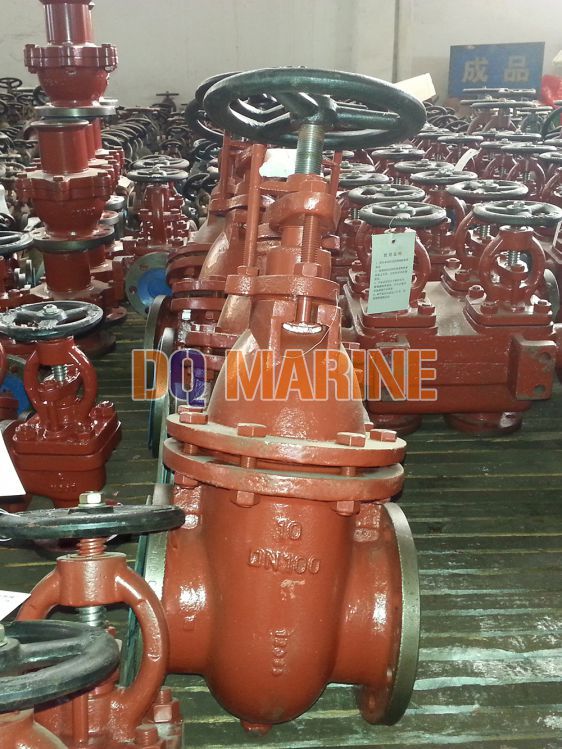
Flanged Nodular Iron Gate Valve for Oil Tanker CB/T3591-2005:
China Flanged Nodular Iron Gate Valve for Oil Tanker CB/T3591-2005:

Nodular Iron gate valve CB/T3591 is used on the fuel transfer system or stripping system for oil tanker, with the medium crude oil, product oil, sea water & fresh water.
Technical Specification:
Design Standard:CB/T3591-94
Test Standard: GB600
Flange size as per GB569 or GB2501
Hydraulic Test Pressure: 1.5Mpa for body, 1.1Mpa for sealing.
| Type | Nominal pressure (Mpa) | Nominal diameter (mm) | Applicable medium |
| A,AS,B,BS | 1.0 | 80~400 |
crude oil, product oil, sea water & fresh water |
Type A---flange size as per GB569, with hand wheel, suitable for deck and pump room
Type AS-flange size as per GB2501 with hand wheel, suitable for deck and pump room
Type B---flange size as per GB569, without hand wheel, suitable for oil tank
Type BS-flange size as per GB2501 without hand wheel, suitable for oil tank
Main Parts & Material:
Body-Nodular iron
Bonnet-Nodular iron
Disc-Cast steel
Stem-Bronze
Nut-Bronze
Seal Ring-Stainless Steel
Main Size List(mm):
For Type A,B (Flange size as per GB569):
|
nominal diameter |
Structure Dimension |
Thickness δ |
Flange | Bolt | stem |
hand wheel D0 |
Lift Range m |
Weight (kg) |
|||||||||
| L | H | ||||||||||||||||
| A | B | D | D1 | D2 | d0 | b | Th. | n个 | d1 | S | A | B | |||||
| 80 | 220 | 440 | 375 | 9 | 170 | 138 | 118 | 15 | 16 | M14 | 8 | Tr26×10(P5)LH | 19 | 200 | 92 | 38.7 | 36.8 |
| 100 | 230 | 470 | 400 | 10 | 190 | 158 | 138 | 15 | 16 | M14 | 8 | Tr26×10(P5)LH | 19 | 200 | 112 | 44.5 | 42.6 |
| 125 | 245 | 515 | 445 | 11 | 215 | 183 | 164 | 15 | 16 | M14 | 10 | Tr28×10(P5)LH | 22 | 225 | 138 | 56.5 | 54.0 |
| 150 | 260 | 560 | 470 | 12 | 240 | 208 | 190 | 15 | 16 | M14 | 12 | Tr32×12(P6)LH | 24 | 250 | 165 | 69.9 | 66.0 |
| 200 | 290 | 660 | 555 | 14 | 310 | 273 | 250 | 17 | 21 | M16 | 12 | Tr32×12(P6)LH | 24 | 280 | 215 | 110.0 | 105.0 |
| 250 | 335 | 780 | 655 | 16 | 380 | 336 | 310 | 22 | 24 | M20 | 14 | Tr36×12(P6)LH | 27 | 360 | 270 | 157.0 | 148.0 |
| 300 | 360 | 885 | 745 | 17 | 435 | 391 | 364 | 22 | 26 | M20 | 16 | Tr44×16(P8)LH | 32 | 400 | 320 | 231.0 | 222.0 |
| 350 | 400 | 990 | 850 | 18 | 485 | 441 | 414 | 22 | 26 | M20 | 18 | Tr44×16(P8)LH | 32 | 450 | 370 | 318.0 | 306.0 |
| 400 | 450 | 1100 | 960 | 19 | 545 | 496 | 466 | 26 | 28 | M24 | 18 | Tr50×16(P8)LH | 36 | 500 | 420 | 370.0 | 355.0 |
For Type AS,BS (Flange Size as per GB2501):
|
nominal diameter |
Structure Dimension |
Thickness δ |
Flange | Bolt | stem |
hand wheel D0 |
Lift Range m |
Weight (kg) |
|||||||||
| L | H | ||||||||||||||||
| AS | BS | D | D1 | D2 | d0 | b | Th. | n个 | d1 | S | AS | BS | |||||
| 80 | 203 | 440 | 375 | 9 | 200 | 160 | 133 | 18 | 22 | M16 | 8 | Tr26×10(P5)LH | 19 | 200 | 92 | 43.2 | 41.5 |
| 100 | 229 | 470 | 400 | 10 | 220 | 180 | 158 | 18 | 24 | M16 | 8 | Tr26×10(P5)LH | 19 | 200 | 112 | 51.3 | 49.4 |
| 125 | 254 | 515 | 445 | 11 | 250 | 210 | 184 | 18 | 26 | M16 | 10 | Tr28×10(P5)LH | 22 | 225 | 138 | 63.9 | 63.7 |
| 150 | 267 | 560 | 470 | 12 | 285 | 240 | 212 | 22 | 26 | M20 | 12 | Tr32×12(P6)LH | 24 | 250 | 165 | 83.3 | 79.2 |
| 200 | 292 | 660 | 555 | 14 | 340 | 295 | 268 | 22 | 26 | M20 | 12 | Tr32×12(P6)LH | 24 | 280 | 215 | 127.0 | 122.0 |
| 250 | 330 | 780 | 655 | 16 | 395 | 350 | 320 | 22 | 28 | M20 | 14 | Tr36×12(P6)LH | 27 | 360 | 270 | 174.0 | 166.0 |
| 300 | 356 | 885 | 745 | 17 | 445 | 400 | 370 | 22 | 28 | M20 | 16 | Tr44×16(P8)LH | 32 | 400 | 320 | 246.0 | 238.0 |
| 350 | 381 | 990 | 850 | 18 | 505 | 460 | 430 | 22 | 30 | M20 | 18 | Tr44×16(P8)LH | 32 | 450 | 370 | 341.0 | 329.0 |
| 400 | 406 | 1100 | 960 | 19 | 565 | 515 | 482 | 26 | 20 | M24 | 18 | Tr50×16(P8)LH | 36 | 500 | 420 | 407.0 | 392.0 |


